
Pipelines and equipment graphs illustrating the processing system are called piping and instrumentation diagrams. The architectural system's design is built on these two-dimensional schematics.
Organizations handling every standardized engineering project must include them. A plant's or a manufacturing facility's specialized operations are described in depth in piping and instrumentation diagrams, which also include symbols for piping fittings, actuators, flow components, instrumentation, equipment, valves, and other items.
P&ID diagrams use a variety of technical symbols that are used in the industry to denote the necessary tools, machinery, pipes, and connecting lines. For a user to comprehend P&ID diagrams, they must be aware of what the various symbols mean.
 |
| P&ID |
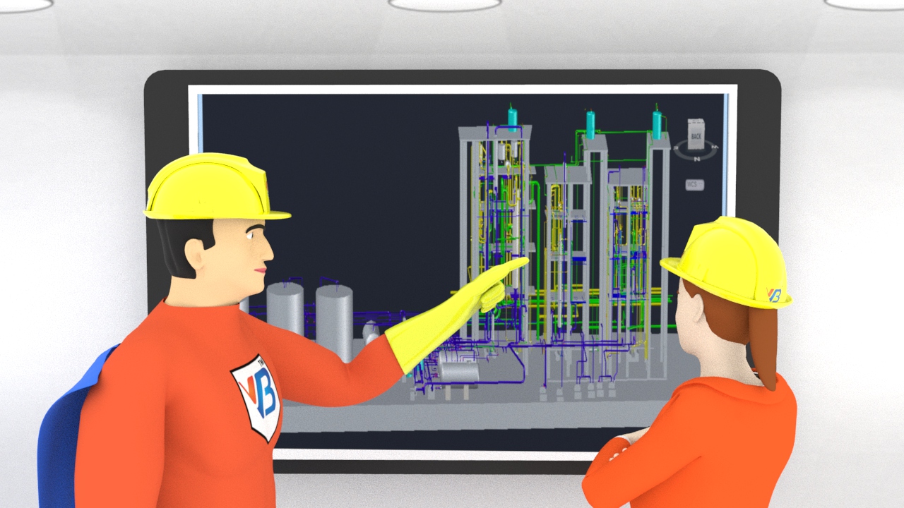
VB Engineering’s Version Of The P&ID Drawing:
The term "piping and instrumentation diagram," also known as "P&ID Drawing," is employed to describe the complete engineering process, such as from the generator (machine/equipment) to the departure point (end utilization), with a critical parameter of the medium employing manual and digitization influencing, ultimately leading to the maintaining of a balance of the entire production process. This is another name for a schematic drawing that is commonly used in engineering.
The process flow industries make use of schematic drawings. P&ID drawings provide more information on a variety of items, including equipment, valves, instruments, gauges for safety, pressure-reducing components, and others. These objects are all used efficiently in process industries to produce goods at a high rate.
VB Engineering’s Strategy To Create Process And Instrumentation Diagrams:
Level 1: Visiting The Site And Gathering Data
It varies depending on the task and what information is needed from the site before designing the 3D pipe model in software. When designing a project, it is necessary to provide specific details.
The primary information VB Engineering believes or predict is
● The basic method of sequencing
● Material characteristics and other details
● Equipment connectors for inlet and outlet
● Several devices used in the sequential procedure
● Employing devices and valves that are both manual and automated in between pipe connections
Level 2: Developing The Design Model
The primary order of procedures must be followed to develop the design model.
● Project Development: This is the first stage in building a project and is followed by the process that creates the P&ID drawings or model.
● Constructing A Template: Before creating this template, we need to determine if the model is 2D or 3D and what kind of piping is used.
● Erecting Buildings: All the equipment and gadgets are supported by a framework that extends from the bottom to the top. Therefore, if the model is 3D isometric, create a 3D model of the structure.
● Constructing Tools: Create each piece of equipment that will be used in the process, such as the heat exchangers, tanks, and vessels.
● Incorporating Specifications And Catalogs: We must assign numerous specific pieces of information to the developed 3Dmodel, including make, size, material, and other flow factors.
● Piling Up Pipes: The main responsibility for 3D isometric P&ID drawings is operating the pipe. Pipelines must be run to their target without colliding with any structures or other equipment.
● Fitting, Valve, And Pipe Support Additions: Other pipe-connected devices have been added to the overall flow line to control the flow of fluids and other media.
Level 3: Exporting For Submission And Approval
After the overall 3D model has been designed, it must be exported for submission and approval.
● Isometric Drawing Creation: For a clearer view of the structure and pipe routing, the 3D-generated model is transferred to 3D isometric drawings.
● Orthographic Illustrations: In 2D orthographic drawings, the extent and volume of the pipe are detailed together with the space allocated for the entire construction.
● Reports Generation: With BOQ, total statistics for the intended model are created.
Pick Up The Pace With Your Digital Twin Partner:
VB Engineering provides a skilled team of specialists for P&ID drawings. Whether you require a process and instrumentation diagram/design or a pipe and instrumentation diagram, our staff is knowledgeable and experienced to meet your P&ID demands.
VB Engineering is your one-stop shop for all of your P&ID drawing needs. As part of our P&ID solutions, we gather readings and data on-site, digitize the system using a library, and create a complete P&ID digital twin version for the plants.

0 Comments